March 25, 2012

MSP-EXP430FR5739 FRAM Speed now!

Review of MSP-EXP430FR5739
first of all i like to give a big thanks to  Farnell/newark http://uk.farnell.com / http://www.newark.com for providing this development board for the review :) http://www.newark.com/texas-instruments/msp-exp430fr5739/msp430fr57xx-fram-device-experimenters/dp/45T9740
FRAM is the next giant leap in Ram technology and im really excited to see all the applications and devices that will include all the awsomeness! 
Aside from being the new really cool technology FRAM is faster more efficient and ultra low-power!. TI's MSP-430 line has been pushing low power applications as one of their main benefits and with the MSP-EXP430FR5739 development board with FRAM technology its possible to achieve all new frontiers of low-power usage 
Board just arrived from Newark!


When i got my board i opened it up and immediately wanted to check out all the cool features. This board definitely has some appreciated bells and whistles. 

  • Integrated MSP430FR5739 :
    • 16KB FRAM / 1KB SRAM
    • 16-Bit RISC Architecture up to 8-MHz
    • 2x Timer_A Blocks, 3x Timer_B Block
    • 1x USCI (UART/SPI/IrDA/I2C ) Blocks, 16Ch 10-Bit ADC12_B, 16Ch Comp_D, 32 I/Os
  • 3 axis accelerometer
  • NTC Thermister
  • 8 Display LED's
  • Footprint for additional through-hole LDR sensor
  • 2 User input Switches
  • Connections
    • Connection to MSP-EXP430F5438
    • Connection to most Wireless Daughter Cards (CCxxxx RF)
The main Stuff that i really like having included is the Accelerometer and the 8 LEDs, which are a pretty bright blue!.


The board came with a 32khz crystal micro USB cable and two female 12pin PCB connectors.
However i have to say that on my board the board came with two male PCB connectors soldered on board. I would prefer the female ones be soldered on the board because while holding the board its easy to touch the male pins and cause some of the readings to be inconsistent, that is why i generally put the female headers on even with the Launchpad. The USB cable is a bit short as well only about two feet but i have tons of these cables around to use instead.

FRAM technology is pretty amazing Its write endurance is ridiculous with 100 trillion write cycles you could write to this at max speed and still not burn it up for thousands of years! Even its write speed is 100 times that of flash with no charge pump it can reach 250x less power than a flash write cycle. pretty nice!

This is one of the built in test modes it shows an LED lighting up fro every 100kb of data in flash speed.
as yo u can see it takes a bit to write each block of 100kb at flash speeds :( 


This video shoes an LED for every 100kb in FRAM speed! really ...really fast


Flash GUI Speed,here you can see how fast the Flash block would die if you were stress writing it.


FRAM GUI speed! Notice that the endurance is crazy eve at top speeds!


Did i mention it has an  Accelerometer !?!

Overall this board is pretty nice to test out new FRAM technology and play around with rapid value writing to the board :) The main thing that erks me is that there is currently no DIP package for any FRAM mcu from TI so hobby development is currently stuck with hard to solder packages that might limit the ammount of home-made applications you will find. The FRAM technology shows alot of potential to be the next gen of wireless and lowpower memory and i cant wait to think to see what it will be applied to. If anyone has any ideas send me an email or comment on a FRAM project idea. Once again i have to thank farnell/newark http://uk.farnell.com / http://www.newark.com for not only suppling the board but having an awsome website where i can get alot of awsome parts for my projects! :)

January 12, 2012

Light Box


See all the photos from this project in the Light Bar Album

For my first big project with the MSP430 i wanted to do a simple RGB light fader. Having only really used an arduino MCU before i just assumed that the MSP430G2231IPN14 Would have a few PWM channels...I was wrong after reading the data sheet i realized that my chip only had one true PWM output :( /cry. So already having bought my 20 RGB LEDs i said that i would find a way to make this work :)
I started wiring All 20 RGB LEDS to some hardboard.Thats 20 RGB pins plus a ground for each LED so 80 different wires and solder points....this took me awhile
Cleaning Up my mess a bit


I started making the power board and quickly learned that there was a lot more to driving all these guys with one PWM channel that i thought i threw in a multiplexer IC and had to do some voltage conversions but got it working pretty well :) (Excuse the fail soldering and wiring)
To make that one PWM seems likes it controlling three different channels i had the MSP430 Rapidly switch the multiplexers out put to each channel making it seem like i had three individual channels. Granted there a some issues with flicker as it tries to fade each channel switching all three channels.

                                                   Mounted with hot glued hardboard case


Tiny Schematic file you can see the Full Sized one in my Light Bar Album 
I had finished this project awhile back so the schematic and most info is to the best of my knowledge...i don't keep very good notes :( but will definitely have better documentation in the future


Testing the partially build green channel had a dead LED in corner that i had to replace :(

The coding to get all the fading took me a while as I'm pretty fail at coding especially considering this is my first big MSP430 project the Arduino made me soft lol. I went with a single push button that gave 12 modes that you have to cycle through.
    

  1. Random combinations of colors Fading up then Down
  2. Red
  3. Green
  4. Blue
  5. Teal
  6. Purple
  7. Fading Red
  8. Fading Green
  9. Fading Blue
  10. Fading Teal
  11. Fading Purple
  12. PARTY MODE!


Party Mode was kinda of a happy mistake i made when trying to do you normal fading. I had selected a random number for the color and delay and it made a frantic strobe like Fade. it looked kinda cool so i kept it in to induce seizures in people passing by :)

The end result is quite pleasing and gives my room a futuristic random light fade in mode 1 :)


PARTY MODE!


I Still have tons to learn with my MSP430 but i had a lot of fun making this project. Learned that i need to work on my electronics hack-fu but i have many more projects in mind.

July 24, 2011

Basic Control Panel

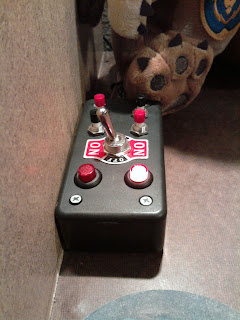
For my first Post project i made a quick control panel just so i could be even more lazy. This will just be a set of switches that control various lights throughout the room. The desk that i built for my electronics didnt really work well with my computer tower so i had to put it under the desk blocking off the power button. This control panel was the solution to that.
It Currently controls

  • Main Desk Lights                 Bottom right Illuminated switch
  • Main Room Light                  Bottom Left Switch
  • Rope Light/Night Light       Center Toggle Switch
  • PC On/OFF                            Right Red Button
  • Overhead RGB Light Bar   Right Black Button
The Top Buttons are AUX for future projects.


Overhead View Of switches

Left Button Controls main desk light but its illumination is a HD activity indicator for PC.


Main Room Light is just a 7 dollar 250w worklight From Home Depot Mounted to the wall. Still provides a pretty good amount of light though :)


Main Desk lights Currently on with Computer